With the advancement of modern microelectronics computers, technologies such as machine, electricity, and liquid (gas) integration, and at the same time, the fuel economy and emission requirements of vehicles, as well as the driver's convenience, comfort, and reliability requirements for automobiles. Under the increasingly high situation, the advantages of automatic mechanical shifting technology have become more and more prominent. This technology has become a hot spot for auto parts suppliers and vehicle manufacturers all over the world. AMT (Automatic Mechanical Transmission) has the advantages of high efficiency and low cost in the automatic transmission, and its application range is wider and wider.
Currently, there are three types of actuators that are widely used in AMT systems: motor actuator solutions, hydraulic actuator solutions, and pneumatic actuator solutions. The motor execution scheme has the advantages of low cost, few components, direct use of the on-board battery as a power source, and no additional equipment. The main disadvantage is that the unit output power is small; the hydraulic scheme is mature in technology, high in reliability, high in processing requirements, high in cost, complicated in structure and many auxiliary parts; and the pneumatic control structure is simple, low in cost, high in reliability, less in auxiliary parts, and free from pollution. Etc., the gas has high compressibility and is difficult to control accurately. According to the characteristics of clutch control in air control AMT system, the gas-liquid integrated clutch control system is designed. The structure, principle and control strategy of this system are introduced and verified by real vehicle test.
aim of design
Clutches are an important part of AMT system control. The speed of clutch combination plays a key role in the driving performance, comfort and safety of the whole vehicle. Most of the current AMT systems use electric motors or hydraulic cylinders to directly drive the clutch, and a separate high-power motor or hydraulic source is required. The failure to fully utilize the gas source provided by the vehicle greatly increases the piping, equipment and cost, and also increases the point of failure of the AMT system. If pneumatic control is adopted, it is difficult to accurately control the gas, and it is difficult to meet the actual needs by using the gas-controlled clutch alone.
In response to the above problems, a gas-liquid integrated clutch control system was designed. The system not only satisfies the overall cost, but also satisfies the precise control of the clutch in the AMT system.
Structural principle
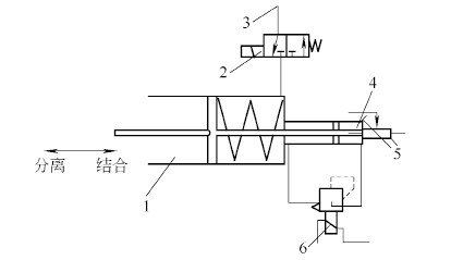
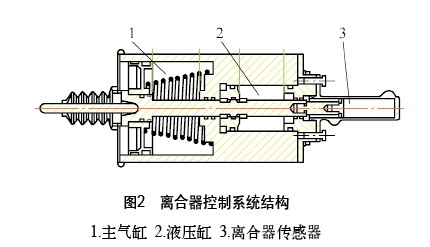
The schematic and structure of the system are shown in Figures 1 and 2, respectively. The pneumatic control clutch automatic control system is mainly divided into five parts: main cylinder (disengagement clutch actuator), hydraulic cylinder (disengage clutch limit, precise control clutch combined with actuator), clutch sensor (feedback clutch stroke), pneumatic solenoid valve ( Main cylinder intake and exhaust control), hydraulic proportional valve (precise control of clutch stroke).
(1) Combination of initial clutch state The pneumatic solenoid valve is closed, and the hydraulic proportional valve is opened to ensure that the hydraulic cylinder is connected to the left and right.

Figure 1 shows the principle
1. Main cylinder 2. Pneumatic solenoid valve 3. Vehicle air source 4. Hydraulic cylinder
5. Displacement sensor 6. Hydraulic proportional solenoid valve
(2) Clutch separation process The pneumatic solenoid valve opens the intake air. When the clutch is just completely separated, the hydraulic proportional valve and the pneumatic solenoid valve are closed at the same time. At this time, the left chamber of the hydraulic cylinder is resisted by the piston pressure to prevent the clutch from continuing to separate, so that the clutch remains current. position.

(3) The clutch is combined with the pneumatic solenoid valve to close, the main cylinder is exhausted, the hydraulic proportional valve is still closed, the hydraulic cylinder piston moves to the right, the right chamber is pressed, the right chamber hydraulic oil is larger than the left chamber, and the clutch coupling speed is controlled by the right chamber hydraulic oil pressure. Size control, at this time by controlling the hydraulic proportional valve, to achieve the speed of the clutch combination.
Considering that the liquid elastic modulus is 2.1×10⁹ MPa (the air elastic modulus is 1.4×10⁵ MPa), the compressibility is almost negligible, so as long as the hydraulic valve starts to operate, the piston can be stopped and the clutch position can be accurately controlled.
Control Strategy
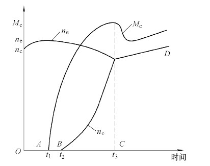
During the control of the clutch, the clutch is disengaged quickly to avoid increased clutch wear and shorten the shift cycle. The clutch is divided into a separated state, a slipped state, and a combined state (see Fig. 3).

Figure 3 Curve during clutch engagement
Ne: engine speed Mc: friction plate transmission torque nc: friction plate (transmission input shaft) speed
It can be seen from Fig. 3 that the clutch is in the disengaged state from 0 to t1, and the action of the clutch should be fast, reducing the power interruption time of the vehicle. From t1 to t2, the clutch is in the slip state. At this time, the combined action of the clutch should be slow, ensuring a smooth transition of the engine speed to the input shaft speed of the transmission, and increasing the smoothness of the combination. T2 ~ t3, the clutch is in the final combination stage. At this time, the transmission input shaft speed and engine speed are consistent. At this moment, the clutch should be combined as soon as possible.
When the clutch is disengaged, the pneumatic solenoid valve is opened to keep the solenoid valve working continuously for the purpose of rapid separation. In the 0~t1 time of the combined clutch, the pneumatic solenoid valve is closed, and the clutch return spring generates the maximum restoring force, so that the clutch is quickly combined. T1~t2, using the working state with duty cycle of 0.4, makes the solenoid valve work indirectly. Since the thrust of the cylinder is less than the restoring force of the spring, the clutch is slowly combined until it is completely combined. The ECU (Electronic Control Unit) makes a logical judgment on the system, converts the processing information into a circuit switch signal, controls the operation of the pneumatic control solenoid valve, selects the air inlet through the on/off of the solenoid valve, thereby controlling the movement of the master cylinder to achieve rapid The purpose of separation. In the process of integration, the ECU also issues a control current signal to the hydraulic proportional valve, and in conjunction with the sensor, the action execution is fed back to the ECU data, and the ECU performs a logic determination. The data values ​​are continually corrected to achieve the combined properties of 0 to t3 in the combining process. The clutch automatic control function is realized by continuously performing the above cycle.
Test verification
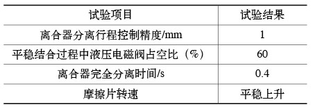
In order to verify whether the gas-liquid integrated clutch control system can meet the demand, the system was tested and verified on the Beiben heavy-duty truck. The 430-pulley clutch was used, and the total weight of the vehicle was 20t. The main results of the test are shown in the attached table. From the test results, the gas-liquid integrated clutch control system meets the requirements of the AMT system.
Clutch control system test results

Conclusion
Since the pneumatic clutch is in the process of control, it is easily affected by gas pressure, temperature and its own compressibility. When the speed is 0~2m/s, the starting speed is slower, and the speed is faster and faster until the speed apex is reached. Closed loop control is very difficult under the existing conditions of the vehicle. The gas-liquid integrated design can avoid the shortcomings of the gas-controlled clutch and give full play to the advantages of hydraulic precision control.
Infrared Steam Room
Infrared Steam Room
Guangzhou Aijingsi Sanitary Products Co.,Ltd , https://www.infinityedgehottub.com