1. Foreword
The blade is processed by four-axis CNC machine tool, and the blade type can meet the processing requirements, but the clearing of the UG software can not meet the processing requirements, so it must be manually modified to meet the requirements.
2. Four-axis machine tool and blade clamping method
2.1 Machine condition
The four-coordinate CNC machine tool is a machine tool that is more economical to machine the blade-shaped surface, but the space surface of the blade root connection surface cannot be processed. The four-coordinate machine has only the X, Y, Z and A axes. Without the C axis, the spindle cannot rotate.
2.2 Blade mounting method
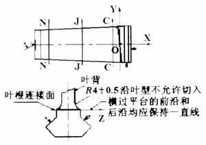
As shown in Fig. 1, the blade is positioned on the bottom surface of the hoe, the back surface is positioned, the basin surface is pressed, and the tip is clamped in a top-tight manner. If the blade shape is perpendicular to the direction of the main axis, that is, the Z axis, the blade root joint surface must be machined with the tool side edge. In this type of clamping, a four-coordinate machine that cannot rotate the spindle cannot machine the shape of the spatial surface.

Figure 1 Blade clamping
3. Blade root condition
There are roughly two types of blades that require clearing, one is a steam turbine blade and the other is a compressor blade.
3.1 Steam turbine blades
The blade type of the steam turbine blade has a large twist angle, and the blade basin and the back curvature are relatively large. The joint of the blade root is generally an angled plane, such as the third stage of the Dongqi and the eleventh stage of the Nanqi, and also the parts connected by the conical surface, such as SAIC's third and fourth grades.
3.2 Compressor blades
The compressor blade is a stator blade with a small blade root angle and a small change in the blade root and tip angle, and the blade shape is gentle. The curvature of the blade basin and the back is small, and the joint of the blade root is a conical surface. Above the airfoil, the middle of the joint is low and the sides are high; the other is the larger the twist angle of the blade root, the larger the twist angle of the blade root and the tip, the twisted rotor blade, the leaf basin and The curvature of the leaf back is small, and the joint of the blade root is also a conical surface, but the axis of rotation is below the blade head, so the middle of the joint is high and the sides are low.
4. The function and limitation of UG software Zhongguanzi leaves clearing root
UG software is a powerful software that integrates CAD/CAM/CAE, but it is a general-purpose software after all, with its limitations and shortcomings. To make it meet the requirements of blade processing, it can be achieved by modifying its program.
The root-cutting method uses a multi-axis milling or a fixed-contour machining method in the processing module in the software.
4.1 Multi-axis milling
Multi-axis milling can be applied to the two blades of the compressor described above, but for the programming needs, the root profile of the part should be re-applied, that is, the blade root surface is offset equidistantly from the blade direction to three The four curved surfaces and the intersection of the blade profile are connected to the curved surface by the THROUGHCURVES function of the curved surface. This curved surface is derived from the blade profile and must be consistent with the blade profile, so it can be used as the geometry of the root processing.
Operation process: enter the multi-axis milling of the machining module, select the drive surface (surfacearea) mode drive, click the new machining surface, select the machining direction, the forward tilt angle and size, the machining accuracy and the number of machining cycles.
4.2 fixed axis milling
Fixed-axis milling can be applied to the steam turbine blade described above. It uses Boundary, and the blade and the back of the blade are processed by one side. Therefore, the boundary line should be made, and the shape and size should be parallel to the wire frame trend of the blade. And the tool allows the tool to pick up the requirements of the part face during machining.
Operation process: enter the fixed-axis milling of the processing module, select the boundary drive mode to drive, click the boundary curve as the closed boundary line frame, select the parallel line mode, step distance, angle and projection direction, and then select the blade shape as the processing geometry. The tool path program is generated. If the connection surface is relatively large, it can be serially connected into a machining program by sequentially changing the tool path generated by the machining allowance to realize the processing of one layer of peeling.
4.3 Processing effect and its defects
Since the root is to be used as a processing reference, the margin is generally large, so it is impossible to use only one knife to clear the root. It is necessary to consider adding coarse roots and semi-precision roots, that is, the balance of several procedures should be consistent. The trajectory of the knife should be connected in a coherent manner. The knife radius of the last root knife must match the radius and size of the root on the drawing.
The height of the blade joint surface processed by the fixed-axis milling program can roughly meet the requirements of the process specification, but the surface of the joint between the pot and the back rail is large, and the subsequent polishing process is not easy to handle.
The tool path program generated by the variable axis milling is displayed in two dimensions with the tool, and it can be seen whether it is overcut. Generally speaking, the tool path is “8†shape. When the overcut occurs, some positions are far away from the curved surface. The highest point of the milled part is 2mm~3mm from the final size, which is far from the processing requirement. And the larger the tool, the larger the error value.
5. Solution
After many studies, there are more feasible ways to improve the roots of various blades, so that the four-coordinate root clearance can meet the requirements of the process specification as much as possible. The following are several classifications of improved programs, all of which are processed using UG software and vericut software.
(1) For the stator blade of the compressor, since the blade shape is relatively straight, it can be directly modified*. The value of X in the cls tool path source file makes the tool track no longer overcut to meet the processing requirements.

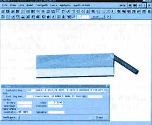
Figure 2 Blade overcut simulation
(2) For the compressor rotor blade, since the blade shape is relatively twisted, if only the X value in the tool path source file is changed, the root portion is lowered, but the blade shape is overcut. Therefore, you can't just change the X value. You must change the Y, Z, I, J, and K values ​​together. That is, you can replace the program that has not been cut. The X value (absolute value) is larger, Y. The values ​​of Z, I, J, and K are similar, which are consistent with the law of up and down changes. However, this program can be from the same position of the previous lap, or the same position of another program, provided that the front and back phase difference can not be too large, the tool changes greatly, and the knife will suddenly break when the knife is suddenly increased during actual processing. The following is the modification method of the φ10 ball cutter rooting processing of 117E3547.
If there is no modification, the overcut will be found during the simulation, as shown in Figure 2.
The corresponding program can be in *. Find out in the cls file, the following is the block that has been cut:
GOTO/-4.6887, 57.5805, 0.7579656, 0.6522945
GOTO/-4.6094, 61.7648,
GOTO/-4.6509, 76.2829, -9.0689, 0.0000000, 0.9715582, 0.2368009
After simulation and UG software, the entire program is X value
Add a program with an approximate Y value, and finally change it to:
GOTO/-4.7033, 57.5793, -1.4600, 0.0000000, 0.7579389, 0.6523255
GOTO/-4.7076,61.7631,-3.3113,0.0000000,0.7677878,0.6407042
GOTO/-4.7481,76.2821,-9.0410,0.0000000,0.9713565,0.2376270
6. Effect and conclusion
Although the program modified by the above method, the effect is not as realistic as the five coordinates, but the cutting allowance has been reduced as much as possible, and the cutting frequency and the workload of the polishing worker are reduced, and the four-axis milling plane function is fully exerted. Come out. And the program has been modified by the above, once it is compiled, it can be used repeatedly, without modification, and achieves the goal of once and for all.
MDF Medium Density Fiberboard Sale Wood Style Surface Interior Furniture board
Medium Density Fiberboard,Osb Board Laminated Particle Board 9mm,High Quality Osb Board,High Quality Lsb Board
Linyi Lanshan Weipu Rubber Factory , https://www.weipuwood.com