Research on Casting Technology of Heavy Duty Truck Bracket

The heavy-duty truck brackets are installed at the two ends of the front axle of the vehicle and support the whole vehicle. They are important components of the chassis parts of heavy-duty trucks. They are subjected to vibration and impact during work, and are subjected to large loads, requiring castings to be in important parts. There must be no shrinkage or shrinkage defects. Through the casting simulation technology, the casting process of the design is simulated, and some suggestions and suggestions are proposed for improving the pouring system and the exhaust system, thereby improving the process design level and reducing the occurrence of casting defects.
1. Structural features of the bracket
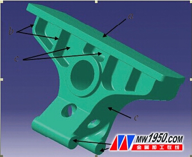
The three-dimensional solid of the stent casting is shown in Fig. 1. The casting is center-symmetrical. The large plane (a) and the middle circular hole are connected by the rib (c), the reinforcing rib (b) serves as an auxiliary support, and the two φ60mm round bars ( At d), the intersecting ribs are connected with the middle ring hole, and the small hole at the lower end of the middle ring hole is a cavity surrounded by the ribs, which acts as a weight reduction. The casting has a simple structure, but the partial wall thickness is thick, the thickest part (e) is 72mm, the maximum outer dimension is 770mm×435mm×300mm, the casting weight is 117kg, and the material is ZG310-570.

Figure 1 bracket 3D solid
2. Bracket original casting process plan
Due to the high melting point of the cast steel, the fluidity is poor, the shrinkage is large, and it is easy to be oxidized, and the inclusions have a serious influence on the mechanical properties of the castings. The bottom pouring ladle is often used, and the cast steel castings should adopt an open casting system.
Because the middle injection type pouring system has the characteristics of stable filling, strong resistance to air hole and slag, and strong anti-shrinkage, shrinkage and leakage, according to the production equipment of our company, the middle injection type pouring system is used. Two pieces, the molten steel directly enters the mold from the side riser.
In order to ensure the full feeding of the casting, three side risers and one top riser are used to supplement the different hot joints.
The core is made of phenolic resin sand. Because the amount of gas generated by the resin sand is large, the sand core forming the position of the middle ring hole is hollowed out, and an air hole is placed at the top of the upper core head, and the upper end of the top riser is pierced for easy discharge in time. The gas in the mold.
According to experience, in order to prevent shrinkage and shrinkage defects at the maximum thermal joint position (e), four external cold iron chills are placed at this position.
3. Filling and solidification process simulation
We use Catia 3D design software to physically model the original casting process, then convert it into STL format file and import it into casting process design and process simulation software CASTsoft. We use the processing module to simulate the solidification process of the process plan and compare the simulation results. Analysis, predicting the size and location of defects.
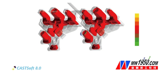
It can be seen from Fig. 2 that when the solidification process of the casting is 52.44%, there are five independent liquid phase zones inside the casting: the largest one at the three side risers and two at the outer cold iron position, and the top riser. One place and a farther from the top riser φ60mm round bar in the middle of the hot section.

Figure 2 Cooling time t = 180.68s The solidification process is 52.44%
The independent liquid phase areas near the three side risers are large in size and are connected in one piece without being disconnected, indicating that the effective feeding distance of the single riser is greater than the distance between the two risers. From the solidification results, the shrinkage and shrinkage cavities in the large plane position appear in the riser, and there is no shrinkage or shrinkage in the casting.
The two independent liquid regions near the outer cold iron are not completely separated from the independent liquid phase formed by the intermediate side riser, indicating that the intermediate riser still has a certain feeding effect on the position. With the further solidification of the molten steel, when the solidification process is about 66%, the independent liquid phase exists in the vicinity of the outer cold iron, but the volume of the independent liquid phase is small, indicating that the external cold iron has a significant effect on the location of the cold.
In the independent liquid phase of the top riser position, shrinkage and shrinkage holes appear in the riser, and no shrinkage or shrinkage occurs inside the casting.
Looking at the whole solidification process, it can be found that when the solidification process is about 25%, the ribs in the middle of the upper and lower φ60mm round bars have partially solidified, and the top riser is interrupted to the channel of the φ60mm round bar that is far away from the top riser. It is supplemented. The independent liquid phase zone at the φ60mm round bar away from the top riser has a large volume, and there is no riser feeding or cold iron chilling, and finally shrinkage and shrinkage hole defects will be formed.
4. Process plan improvement and simulation
Through the simulation analysis of the solidification process of the original process scheme, it can be seen that the castings of the three side risers, the outer cold iron and the top riser have no shrinkage and shrinkage defects, but the middle part of the φ60mm round bar away from the top riser. A large shrinkage hole defect has appeared. In order to eliminate the shrinkage hole defects of the casting, it is possible to try to place two inner cold irons in the center of the φ60mm round bar and the final disappearance position of the independent liquid phase zone; at the same time, the three side risers are close to each other, and the effective feeding distance of the single riser cannot be fully utilized. The feeding effect, and the intermediate riser has a certain feeding effect on the independent liquid phase at the cold iron. It is possible to try to remove the symmetrical side risers at both ends, leaving only the intermediate side riser, and if necessary, appropriately increase the middle side The size of the riser increases the effective feeding distance of the riser.
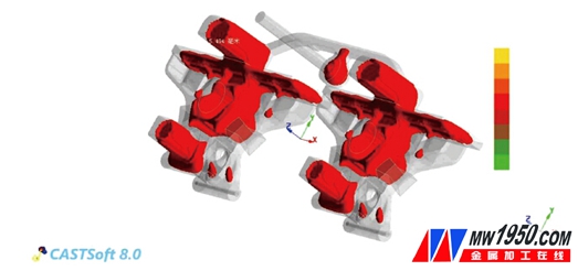
The process plan was improved by adding two inner cold irons at the φ60 mm round bar away from the top riser to remove the symmetrical side risers. The modified process plan solidification simulation results are shown in Figure 3.

Figure 3 Cooling time t = 154.94s The solidification process is 45.06%
It can be seen from Fig. 3 that when the solidification process is 45.06%, the intermediate side riser always has a supplementary effect on the large plane in its effective feeding distance, and also has a certain complement in the independent liquid phase near the cold iron position. Shrinkage. From the solidification results, the shrinkage and shrinkage cavities in the large plane position appear in the riser, and there is no shrinkage or shrinkage in the casting. Under the common chilling effect of two internal cold irons, when the solidification process has not reached 50%, the nearby molten steel has completely solidified.
5 Conclusion
Through the actual process verification, no shrinkage or shrinkage defects were found in the five independent liquid phase regions appearing in the solidification simulation. The casting process solidification process simulation has a strong guiding role in the design of new products. Through the simulation of the solidification process of the original casting process plan, the size and position of the defects are found, and the corresponding technological measures are formulated to improve the success of the casting process design. Rate, shortening process development time and increasing productivity.
About the author: Zhang Fubin, Gao Xiuwu, Dai Fangzheng, Wang Chengliang, China National Heavy Duty Truck (Hong Kong) Co., Ltd. Jinan Casting and Forging Center.

Towel Bar

A Towel bar is an easy way to keep your bathroom looking tidy, while helping your towels dry more quickly. Different towel bars can accommodate more towels, whether you're looking for a single or double towel bar. And most towel bars are wall-mounted. You can buy your bathroom towel bar in a range of finishes to match other bathroom accessories, such as chrome towel bars, brushed nickel towel bars, gold towel bars, or even modern matte black towel bars.

Towel Bar,Towel Bar Supporing Chrome,Washroom Towel Bar,Height of Towel Bar

Kaiping Jenor Sanitary Ware Co., Ltd , https://www.jenorsanitary.com