1 Introduction
With the continuous development of high-speed machine tools and the continuous improvement of the performance of cutting materials, in order to meet the high-speed, high-efficiency production requirements, the spindle speed of the machine tool is also getting higher and higher. Whether it is the traditional ISO spindle/shank connection or the HSK spindle/shank connection that has appeared in recent years, the spindle and the shank will expand radially under the action of centrifugal force during the cutting process. In the case where the main shaft and the shank are made of the same type of material, the former's expansion amount is always greater than the latter, thereby reducing the reliability of the joint; if the material properties of the main shaft and the shank are not properly matched, the consequences will be more serious. The above changes are generally neglected at the usual rotational speeds, but when the rotational speed is high, the radial expansion caused by the centrifugal force reduces the contact stress between the joint surfaces, resulting in a change in the position of the shank relative to the main shaft and the role of the cutting force in the radial cutting force. Bending underneath directly affects machining accuracy and surface roughness.
The spindle/shank connection is a highly nonlinear contact problem with boundary conditions, and the contact surface exhibits a complex contact state and stress state. The traditional methods based on Latin American equations have certain limitations and cannot solve such problems well. In recent years, with the development of computer hardware and software technology and nonlinear finite element technology, researchers have begun to study and simulate the variation of the deformation between the conical surfaces and the contact stress by means of the nonlinear finite element method. In this paper, the influence of centrifugal force on the coupling performance of ISO 40 and HSK-A63 spindle/shank is studied by means of advanced nonlinear finite element technology, which provides a theoretical basis for the design and optimization of spindle/shank joint.
2 Mechanical analysis
The flange diameters of the ISO 40 shank and the HSK-A63 shank are relatively close (63.55mm and 63mm respectively), so these two joints were chosen as the research object.
The spindle/shank connection operating in a rotating state is simultaneously affected by the stress generated by the centrifugal force and the stress generated by the interference fit. If the main shaft and the shank rotate about their central axis at an angular velocity w (whether constant or accelerated), the radial displacement components u 1 (a) and u 2 (a) at the contact between the shank and the spindle taper under centrifugal force Separately
| (1) |
| (2) |
Where c, a - the inner and outer radii of the shank respectively (the inner diameter of the ISO 40 shank c = 0)
a, b - the inner and outer radii of the main shaft
R——material density
E——Elastic modulus
v——Poissonby
Comparing equations (1) and (2), u2(a) is always greater than u1(a), that is, in any rotation state, the radial expansion of the inner bore of the spindle is larger than the radial expansion of the taper of the shank, the spindle There is a radial gap d between the inner hole and the tapered surface of the shank, and the two can never be contacted.
| (3) |
At any section of the conical joint, the relationship between the contact stress p and the interference amount D is as follows:
| (4) |
Equation (4) consists of two parts, the first half being used to create contact stress between the cones and the second half being the radial gap created by centrifugal force. To ensure that the coupling characteristics do not change under high-speed rotation, it is necessary to increase the interference, on the one hand to eliminate the reduction effect caused by centrifugal force, and on the other hand to generate sufficient contact stress between the joint faces to ensure that the shank is in the taper hole Precise positioning and clamping inside.
3 finite element analysis
Due to the axial symmetry of geometry, loads and constraints, a three-dimensional axisymmetric plate element is used to simulate a three-dimensional solid element when performing finite element analysis. A pair of contact points is established between the main shaft and the shank. The friction between the two is in accordance with Coulomb's law. The Newton-Raphson iteration method is used in the solution. The clamping force of the ISO 40 coupling system acts on the rear end of the shank, while the clamping force of the HSK-A63 coupling system acts on the 30° cone of the shank bore.
Deformation analysis
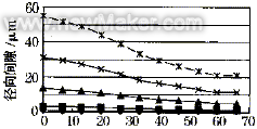
As shown in Figure 1, the radial clearance of the spindle/shank joint increases in a square relationship with increasing rotational speed, and this variation is non-uniform across the contact cone. It can be seen from Fig. 1a that the gap at the large end of the ISO 40 shank is larger than that of the other parts, and the change of the radial gap is a bell-shaped shape, and as the rotation speed increases, the bell mouth trend becomes more obvious: when the rotation speed is 10 000 r/min The large end gap is 3.4 μm, the small end gap is 1.3 μm, and the gap between the large and small ends is 2.1 μm. When the speed is increased to 30 00 r/min, the large end gap is 30.9 μm, and the small end gap is 11.7 μm. Increase to 19.2. Due to the small taper of the HSK-A63 coupling and the hollow structure of the shank, the radial clearance is much more uniform than the ISO 40 connection, and the gap between the ends is not more than 1 μm.


(a) ISO 40 (b) HSK-A63

Figure 1 Effect of rotational speed on radial clearance
Table 1 Tolerances and fits for spindle/shank joints
| specification | Shank | Spindle | Cooperate | |||||||||||||||
| Big end diameter (mm) | Small end diameter (mm) | Big end diameter (mm) | Small end diameter (mm) | Big end (μm) | Little end (μm) | |||||||||||||
| ISO 40 | 44.45 | 25.3 -0.0043 | 44.45 | 25.3 +0.011 | 0 | 0 to 15.3 | ||||||||||||
| HSK-A63 |
|
|
|
| -17~-7 | -14~-4 | ||||||||||||
It can be seen from the above analysis that the shank and the spindle manufactured according to the standard, whether it is the ISO40 connection or the HSK-A63 connection, have the problem of insufficient interference. Therefore, to ensure the reliability of the connection between the shank and the main shaft, it is necessary to increase the interference to offset the reduction effect of the centrifugal force, and form sufficient contact stress on the joint surface to achieve precise positioning and reliable clamping of the shank. .
2. Contact stress analysis
As mentioned earlier, to ensure reliable contact of the spindle/shank joint at high speeds, a large interference is required to offset the gap between the spindle and the shank during high speed rotation. However, excessive interference requires a large pulling force from the broaching mechanism, which is very unfavorable for the tool change, and also causes the end of the spindle to expand, which has an adverse effect on the front bearing of the spindle. Therefore, under the premise of ensuring that the material does not fail, does not hinder the tool change and does not affect the accuracy of the spindle bearing, the interference between the joint surfaces and the contact stress can be improved by appropriately increasing the axial tensile force, thereby improving the reliability and processing of the joint. quality. For ISO 40 connections, Ott's clamps have an axial pull of 10.5kN, Roehm's clamps have an axial pull of 12kN, and Berg's SSK and SSKE clamps have an axial pull of 13kN, while SSKE The axial pull of the -KH clamp is 18kN. According to ISO and DIN standards, the axial pull of HSK-A63 is 18kN.
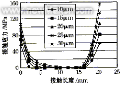
Finite element analysis shows that increasing the interference can effectively increase the contact stress (as shown in Figure 2). If the maximum speed of the spindle is 10 000r/min, the optimal interference of the ISO 40 spindle/shank joint under different tensions (10.5kN, 12kN, 13kN and 18kN) can be obtained separately. 1.85μm, 2.00 respectively. Μm, 2.11 μm and 2.63 μm. For the HSK-A63 spindle/shank connection, if the maximum speed of the spindle is 20 00r/min, the optimal interference is 25~30μm, and the nominal size of the large end of the shank and the spindle is 48mm; According to ISO12164-1, the nominal size of the large end of the tool holder and the main shaft is 48.010mm and 47.988mm respectively, and the optimum interference is 13~18μm.


(a) ISO 40 (speed 10 000r/min) (b) HSK-A63 (speed 20 000r/min)
Figure 2 Effect of interference (axial tension) on contact stress
Under the action of centrifugal force, the deformation and contact stress between the coupling surface of the spindle/shank change with the increase of the rotation speed, resulting in a decrease in the performance and machining accuracy of the coupling system. When the rotation speed is not high, the centrifugal force influence may not be considered, but when the rotation speed is high, it must be fully considered to ensure the reliability of the connection. Increasing the interference can effectively solve the above problems and improve the joint performance and machining accuracy. When the maximum spindle speed is 10 000r/min, the optimal interference for ISO 40 connection is 1.85~2.63μm (axial tension is 10.5~18kN); when the maximum spindle speed is 20 000r/min, HSK-A63 The optimum interference for the joint is 13 to 18 μm (axial pull force is 18 kN).
Outdoor Garden Light is typically used to illuminate areas such as gardens, lawns, pathways, and courtyards. They can be pole-mounted, wall-mounted, or ground-mounted and typically use LED or other energy-efficient bulbs to provide efficient lighting. Outdoor Garden Lights can also be equipped with sensors to automatically turn on or off when detecting people or animals, saving energy and increasing safety. Additionally, they can have different designs and colors to meet various outdoor design needs.
Outdoor Garden Light,Farmhouse Style Steel Outdoor Lamp,Outdoor Wall Lamp Garden Lighting,Garden Pendant Lamp
Zhengdong Lighting Co., Ltd. , https://www.zdlightingfixture.com