|
3 software user interface
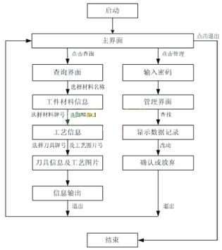
The user interface of the software visualization has the main interface, the user query interface and the management interface. Their role in the human-machine dialogue operation software program is shown in Figure 4. There are drop-down menus or mouse buttons that are commonly used in Microsoft software to provide users with a choice of clicks for easy operation.After starting the database software, the user first comes to the main interface, and can see the name of the unit participating in the research and development database system, and enter the query interface or the management interface through the mouse button. The user needs to quit the program when he finishes the work, and also through the main interface under normal circumstances.
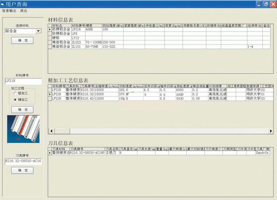
After the user enters the query interface, you first need to select or enter the workpiece material name. The mouse or keyboard action automatically retrieves all the information records corresponding to the material name from the material table of the background database through the ODBC interface, and returns them through the ODBC interface to display on the query interface. Then, you need to click to select one of the material grades and select roughing or finishing. Through the contact and interaction between the query interface and the back-end database, the retrieved process information records will be displayed on the query interface, or there will be no corresponding records. At this point, you need to re-select as finishing or roughing. For the former case, you need to continue to click on the tool number or process picture number to complete the operation of retrieving tool information and process picture information. The craft picture can also be enlarged. Figure 5 shows the user query interface.In the above process, the current operation can be interrupted at any time to return to the retrieval of any previous information, such as abandoning the last tool information retrieval directly back to the selection or input of the next material name from scratch. Once the required data information is retrieved, you can click on the button in the upper left corner of the query interface to enter the information output interface, print them out as screen display, or write (.mdi), web page (html) in Microsoft Office document image. Various file formats such as text (txt) are exported. Data information can also be viewed under the UNIX operating system or in the machine CNC system.
In order to facilitate the modification of process technology data and maintenance system, the software adds a management interface. After entering the password to enter the management community, you can add, update, and even delete data information directly in the running state of the software program, without having to end the program running into the SQL Server2000 platform to complete the operation.
|
4 Accumulation of process technology data
Database system HSM process technical data, currently involving aluminum alloy, copper alloy, steel, cast iron and paper-based honeycomb cores and other types of workpiece materials. Milling cutter materials mainly include cemented carbide and diamond. Among them, a car engine factory and the like use a diamond milling cutter to high-speed milling of aluminum alloy workpieces at a line speed exceeding 3900 m/min, which not only has high processing quality and high efficiency, but also has long tool life and good economic results. In the laboratory, for example, a TiAlN coated carbide milling cutter is used for high-speed hard milling of a hardened steel mold with a hardness of 52HRC. The linear velocity exceeds 200m/min, the surface roughness reaches Ra0.33μm, and the processing time is saved. In these HSM cutting examples, the machine spindle speed is correspondingly as high as 15,000 to 28,000 r/min. Another representative cutting data, feed rate, has reached 6 to 8 m/min in many processing examples.As far as the geometry of the workpiece is concerned, there are multi-ribbed thin-walled monolithic structural parts in the processing example, and the material removal rate is as high as 80% or more. It is necessary to control the processing deformation and improve the efficiency, and the milling paper-based honeycomb core test piece needs to use special Fixtures and milling cutters. In addition, there are complex three-dimensional free-form surfaces in the example, which need to be formed by four-axis or even five-axis CNC milling.
The continuous accumulation of HSM process technology data will continue from these two aspects.5 Outlook
The above high-speed cutting process database has been submitted to the Chinese cooperative enterprise for international cooperation projects for trial use. Through extensive listening and preparation, we are ready to expand into a high-speed cutting process expert system that can be accessed remotely through the network with the support and cooperation of the state, local governments and domestic enterprises.
Previous page
A pneumatic hydraulic jack is a mechanical device that uses air pressure to generate force and lift heavy objects. It cosists of a cylinder and filled with compressed air, a piston that moves up and down inside the cylinder, and a hydraulic system that converts the air pressure into hydrauli force. When the jack is activated, the compressed air pushes the piston, which in turn pushes hydraulic fluid through a series of valves and pipes, creating a force that lifts the load. The jack is commonly used in automotive and industrial applications for lifting vehicles and heavy machinery.
Low Profile Air Jack,Heavy Duty Air Jack,Pneumatic Hydraulic Bottle Jac
Yantai Dongyue Hydraulic Technology Co., Ltd , https://www.deeleap.com

