3. PCD composite sheet high frequency induction brazing test
(1) Test methods and equipment
a. Test Method
After the PCD composite sheet is cut into the desired shape by EDM, the cemented carbide substrate is ground with a diamond grinding wheel, and then placed in an ultrasonic cleaner for cleaning, and then polished with a boring 45 steel arbor and sandpaper. The solder pieces are placed in an acetone solution and immersed for 2 to 4 hours for use. The flux (paste), solder sheet and composite sheet are placed on the 45 steel knife bar in sequence, and then brazed by high frequency induction heating in the air. After the welding, the tool is slowly cooled and then sprayed with a sand blasting machine. Sand to remove surface debris.
The main factors affecting the brazing strength of PCD composite sheet include brazing temperature, constant temperature holding time, and brazing metal surface processing quality. Among them, brazing temperature and constant temperature holding time have the greatest influence on joint strength, which plays a decisive role in welding quality. In order to determine the optimum brazing temperature and time, the following tests were carried out respectively: 1 test of the wetting ability of the brazing material on the 45 steel shank and the cemented carbide substrate (YG8); 2 the relationship between the shear strength and the brazing temperature; The relationship between the shear strength and the holding time of the brazing temperature; 4 the relationship between the shear strength and the surface roughness of the brazing metal.
b. Test materials and equipment
Test materials: 45 steel shank, PCD composite, silver copper solder, 101 flux, acetone solution.
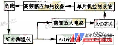
Test equipment: ultrasonic cleaner; tool microscope; shear strength measuring device (homemade); single-chip fuzzy control and synchronous data acquisition system for controlling brazing parameters and collecting test data (developed by itself, structure shown in Figure 2). Domestic GP15-CW6 high frequency induction heating equipment (homemade heating induction coil); American Wahl HSM-672 type infrared thermometer (response time 0.1s). The MCU control system consists of 8031 ​​chip plus various expansion chips and necessary circuits. It adopts Taiwan PCL-818L A/D conversion card, ADC0809 A/D chip, the load is composed of heating induction coil and workpiece; preamplifier circuit is selected. The OP-07 and LM324 amplify the infrared thermometer output signal for analog to digital conversion.

Figure 2 Structure diagram of fuzzy control and synchronous data acquisition system
(2) Test results and analysis
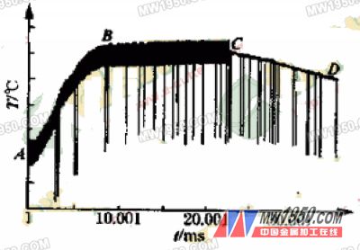
According to the data collected by the system, the heat cycle process diagram of induction heating brazing shown in Fig. 3 can be obtained. In the figure, the abscissa is the heating time t, the sampling time interval is 1 ms, and the ordinate is the output voltage value. Since the output relationship of the infrared thermometer is 1 mV corresponding to 1 ° C, it can be directly labeled with the temperature value T. The section AB of the curve is the heating and heating stage, the BC section is the brazing constant temperature stage, and the CD section is the stop heating stage. The average value of the corresponding data of the BC section is taken as the brazing temperature, and the time corresponding to the BC section is the brazing constant temperature holding time.

Figure 3 Brake process heating cycle data collected by the system
a. Wetting ability of brazing filler metal to brazing metal
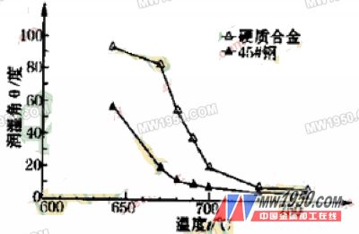
In the formation process of the PCD composite brazing joint, the wetting property of the brazing filler metal directly affects the welding quality, so it is necessary to test and analyze the wetting of the brazing metal by the brazing filler metal. At different temperatures, the same brazing constant temperature holding time (20s) was used to measure the wetting angle of the brazing filler metal to the cemented carbide and 45 steel. The measurement results are shown in Fig. 4.
It can be seen from the figure that for the 45 steel shank and the cemented carbide substrate, the wetting angle decreases as the temperature increases. The wetting angle decreased significantly around 700 ° C, and then the wetting angle did not change much with increasing temperature. The effect of brazing temperature on the wetting angle of the brazing filler metal is greater than that of 45 steel. At the same temperature, the wetting angle of 45 steel is lower than that of cemented carbide, so the wettability of brazing filler metal to 45 steel is better than that of hard alloy, that is, the bonding strength between brazing filler metal and 45 steel is higher than that of hard alloy. . This was also confirmed by the fact that it was observed under a microscope that the shear failure section occurred mainly on the side of the cemented carbide.

Fig. 4 Relationship between wetting angle of brazing filler metal to different brazing metals and brazing temperature
Previous Next
Industrial Model,Model Industrial,Industrial Scale Models,Building Construction Model
Nanjing Great Century Art Model Co., Ltd. , , https://www.dsjysmx.com