Abstract: This paper analyzes the processing difficulties of deep cavity small holes, conducts preliminary exploration and process analysis of the processing method, proposes solutions, and gives specific processing and measurement methods. After inspection, all the indicators of the machined parts meet the requirements of the drawings.

Part structure
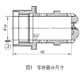
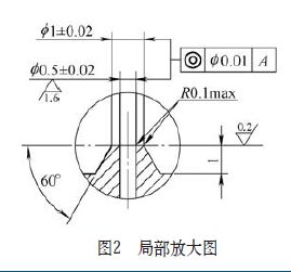
In the product processing and manufacturing tasks undertaken by the author, there is a kind of solenoid valve. In the production process, it encounters a deep cavity small hole problem that cannot be processed according to the traditional method. The depth of the deep cavity and the small hole are not encountered in the past. The specific part dimensions are shown in Figure 1 and Figure 2. The processing of this part is very difficult, and how to ensure the quality of the processing makes us quite troublesome.


2. Processing difficulties analysis
It can be seen from Fig. 1 and Fig. 2 that the precision of the deep cavity small hole is extremely high: φ 16mm for the deep cavity and 40mm for the depth; φ(0.5±0.02)mm for the small hole in the deep cavity, and the top of the small hole The boss-shaped sealing surface, the outer circle φ 1mm, the small hole diameter 0.5mm, the depth 5mm, the coaxiality requirement of the deep cavity small hole and the boss-shaped sealing surface is φ 0.01mm, and the perpendicularity of the boss-shaped sealing surface and the deep cavity is 0.01mm It must be completed in one clamping process, and there must be no deflection, otherwise the pattern requirements cannot be met.
The ratio of the diameter of the deep cavity to the length of the part is 1:10, which belongs to deep hole processing.
Because the depth and diameter of the hole are relatively large, and the small hole is inside the deep cavity, the drill pipe is slender, the rigidity is poor, and the deflection and vibration are easily generated during work. Therefore, the accuracy and surface quality of the hole are difficult to control; Since the part material is 1Cr18Ni9Ti, if the chip breaking is not good, the bit may be damaged due to chip clogging, and the processing quality of the hole cannot be guaranteed.
3. Processing method exploration
In response to this problem, the following explorations were carried out in the previous period:
(1) Customized long drill bit: More than 10 long-distance high-speed steel drill bits and alloy steel drill bits have been customized. Due to the limited toughness of the drill bit, the drilling heat is not easy to dissipate, the chip removal space is small, and it is easy to block. The drill bit is easy to process. Breaking, even if the feed is controlled very small, it cannot be guaranteed.
(2) Using laser drilling technology: the laser drilling machine is used to process the deep cavity small hole. As a result, it is found that the roundness of the small hole is poor. The key problem is that the laser drilling machine must be double-loaded, basically not It is possible to ensure the coaxiality of the deep cavity small hole and the boss-shaped sealing surface to be φ 0.01 mm.
4. Process analysis
Deep hole processing in deep cavities affects the quality of processing in two ways:
(1) Stiffness of the drill bit: The drill pipe is slender and has poor rigidity. It is easy to produce skew, vibration and break during work, which affects the accuracy and surface quality of the hole.
(2) Chip removal: the hole is small and deep, the chip removal channel is long, and it is working under the condition of close closure during drilling. Due to the long time, the chip breaking is not good, and the chip removal is not smooth, it may be blocked due to chipping. The drill bit is damaged and the processing quality of the hole cannot be guaranteed.
5. Measures taken
In view of the particularity of deep hole machining and the requirements for deep hole drilling, the following measures have been taken to absorb the previous experience and combine the characteristics of deep cavity small holes:
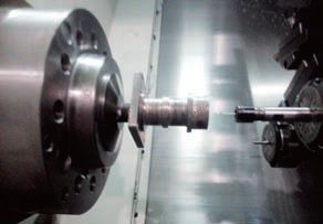
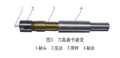
(1) Design the drilling tool loading device to increase the rigidity of the drill bit. The drilling tool loading device uses a wrap-around structure that reduces the exposed portion of the drill bit (see Figure 3) to increase bit stiffness and strength. And the cutting fluid flow channel is set, and the cutting fluid is forcibly discharged by the action of the cutting fluid with a certain pressure to achieve the purpose of chip removal and cooling.

(2) Improve the drilling tool. In order to ensure the surface roughness requirements of the deep cavity small holes, the rough processing of the twist drill is required, and the reamer is used for finishing. In order to improve the toughness of the reamer and prevent the damage of the reamer during processing, the method of halving the number of teeth is used to improve the reamer, reduce the feed amount, increase the chip removal and chip space, and have good toughness and good heat dissipation. And the advantages of chip removal.
(3) The manual feed drilling is realized, which effectively reduces the possibility of the drill bit breaking. Designed with a drill sleeve for manual feed drilling. Even if the processing equipment is very precise, it is mechanically fed, and it is impossible to feed back the cutting force. However, by manual feeding, the proper feed rate can be controlled. Once the cutting force is too large or there is any indication of the deviation of the drill, the drill bit is immediately returned. The clearance between the drill sleeve and the tool body is controlled within 0.005mm, which is especially effective for deep hole machining. This method can process φ 0.2mm small holes on a lathe.
6. Process method
The processing method is as follows: 1 center drilling positioning, axial feeding is completed 6 times, and the last 2 feedings are manually fed. 2 After three empty feeds to deburr, the surface roughness of the small holes is required.
7. Measurement method
In Figure 2, the diameter of the center hole (0.5 ± 0.02) mm and the outer diameter of the boss-shaped sealing surface of the small hole φ 1 mm cannot be directly measured on the processing equipment. The measurement method used by the company is to combine the small-scale tool microscope measurement with the image measuring instrument with the scale after removing the parts.
The first part of the machining is first measured with a small tool microscope with a scale. The microscope can be magnified 30 times. By adjusting the scale line, the dimensions φ (0.5 ± 0.02) mm and φ 1 mm are measured and the measured values ​​are recorded. Then the deep cavity of the part is removed, that is, the outer diameter of the convex-shaped sealing surface φ 1mm is protruded outside, instead of being in the deep cavity, and then measured by an image measuring instrument, the magnification of the image measuring instrument is adjustable within a range of 30 to 200 times, Use 30 times measurement, record the measured value, compare the two measurement results, and measure the value to meet the tolerance requirements for batch processing. Batch parts are 100% measured using a 30x small tool microscope.
8. Conclusion
By adopting the above measures and process methods, the problem that the deep cavity deep hole processing cannot guarantee the processing quality is solved, and the accuracy and tolerance requirements of the small holes are effectively ensured. After inspection, all indicators meet the requirements of the drawings.
Elevator Traction Machine,Gearless Traction Elevator,Geared Traction Elevator,Gearless Elevator Motor
MAURER TECHNOLOGIES CO., LTD. , https://www.maurer-elevator.com