The CimatronCAD/CAM workpiece environment is specifically designed and developed for the mold industry. In addition to providing comprehensive processing applications in the processing field, it also provides users with the most advanced processing technology known as Smart NC. The intelligent NC marks a major technological breakthrough in cimatron's processing. It is well known that the higher the blank retention before high-speed finishing, the better. Although the tool load analysis and optimization after the event can avoid the occurrence of accidents such as chipping or affecting the surface quality of the parts due to excessive excess, but There are many places where there is a large amount of surface, and it is necessary to perform low-speed cutting in many places. This not only affects the processing efficiency, but also does not become a high-speed milling process, and the surface quality after processing is greatly affected. The existence of this technology makes the system search for excess amount between the two layers during the roughing calculation and perform automatic inter-layer reprocessing of these parts (using the sequential contour method, etc.), so that the high-speed fine A very ideal, uniform part surface is obtained before processing. This function not only for high-speed milling but also for traditional CNC milling, it can also reduce the amount of time for roughing and secondary roughing.
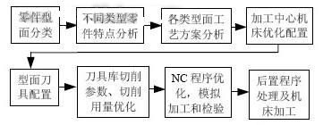
1 Upper mold structure characteristics and CNC machining process design MOTOROLA's four-cylinder electric jet tube mold is divided into four parts: upper mold, lower mold, upper core box and lower core box. This paper analyzes the NC machining process of the upper die, optimizes it and designs the NC machining program. The internal cavity structure of the upper mold is complex, not only has inclined surface, tapered surface, inclined hole, but also complex spiral surface, and the parting surface has curved surface and inclined surface transition. If the traditional processing method is adopted, not only the process is complicated, but also The phenomenon of overcutting and tool collision is generated, and the accuracy is difficult to guarantee. The upper mold is shown in Fig. 1. Therefore, according to the characteristics of the upper mold, the process scheme shown in Figure 2 is proposed.

Figure 1

Figure 2 upper mold processing scheme
1.1 Preparation before programming (1) Introduce the four-cylinder jet pipe mold file under the Cimatron E 4.2 menu and select the appropriate method to repair the damaged surface.
(2) Select Tools - Parameter Settings from the menu to cancel the option to use the advanced working mode.
(3) Under the New Tp Folder menu, select the three-axis CNC milling mode according to the actual situation, and set the machining reference coordinate system with the design reference of the mold shape---the center of the cavity.
(4) Select the upper mold part and blank type to prepare for subsequent processing and inspection analysis. In this article, select the surface and square blank and hook the box before the automatic preview.
1.2 Analysis of the upper mold process The original processing technology of the upper mold is processed by ball cutter, the surface quality is not good, and the processing scheme is single, and the processing time is up to 7 days. So we reset the machining process to reduce machining time and improve the surface accuracy of the parts.
(1) Select a suitable process benchmark. The upper mold has 2 holes and is distributed diagonally. Therefore, the two holes are selected as the positioning reference. Since the two holes have been processed in advance, the machining is not processed in this time control programming.
(2) The profile of the upper die is more complicated. For the convenience of processing, all the faces are divided into four categories: joint faces, straight grooves, cavities and grooves.
1.3 CNC program optimization design is suitable for high-speed milling requirements, Cimatron E 4.2 has a wide range of cutting methods in roughing and fine machining, including surface milling, contour milling, parallel milling and so on. According to the process characteristics of each profile of the upper mold, the following processing flow is formulated:
Next page
Fuel injector simulator is a basic tool for diesel injection service lab.
Injector simulator is used to drive the solenoid of common rail electronic injector, by cooperate with a manual Nozzle Tester, it could test the electronic injector.
Electronic injector simulator could test both solenoid and piezo injector, it support all brands including Bosch, Delphi, Denso, CAT, Cummins, Siemens etc.
Injector Simulator,Crdi Injector Simulator,Common Rail Injector Simulator,Piezo Injector Simulator
CHENGDU UNICO MACHINERY CO., LTD , https://www.injectortestbench.com