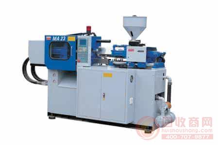
The injection molding machine is a special plastic molding machine that utilizes the thermoplasticity of plastics, melts it by heating, and applies high pressure to quickly flow into the cavity. After a period of pressure and cooling, it becomes a plastic product of various shapes.
The electrical energy consumption of injection molding machines is mainly reflected in the following parts:
1 power consumption of the hydraulic system oil pump;
2 heater power consumption;
3 Circulating cooling water pump power consumption (in the injection molding workshop, generally multiple injection molding machines share a cooling water pump), in which the power consumption of the hydraulic oil pump motor accounts for more than 80% of the electricity consumption of the entire injection molding machine, so reduce its power consumption. Quantity is the key to energy saving in injection molding machines.
First, the working cycle of the injection molding machine
1. Locking mold: The mold pulls quickly close to the fixed mold (including slow-fast-slow speed), and confirms that there is no foreign matter, the system turns to high pressure, and the template is locked (maintaining the pressure inside the cylinder).
2. The shot is moved forward in place: the shot is advanced to the specified position (the nozzle is in close contact with the mold).
3. Injection molding: The screw can be set to multi-stage speed, pressure and stroke to inject the molten material at the front end of the barrel into the cavity.
4. Cooling and holding pressure: According to the set pressure and time period, the pressure of the barrel is maintained, and the cavity is cooled and formed.
5. Cooling and pre-plasticization: The product in the cavity continues to cool, while the hydraulic motor drives the screw to push the plastic particles forward. The screw retreats under the set back pressure control. When the screw retreats to the predetermined position, the screw stops rotating and the injection stops. The cylinder is loosened according to the setting and is expected to end.
6. Shooting back: After the pre-molding, the shooting platform retreats to the designated position.
7. Open the mold: the mold pulls back to the original position (including slow-fast-slow speed)
8, top out: thimbles out of the product.
Second, the energy waste of the traditional hydraulically driven injection molding machine
The hydraulically driven injection molding machine changes the pressure and flow rate required in the above stages. When the oil demand of the injection molding machine changes, the proportional pressure valve and the proportional pressure relief valve at the outlet of the oil pump regulate the load pressure and Flow, providing the thrust, pressure direction and moving speed required for each cylinder and hydraulic motor. The output power of the oil pump is equal to the product of the output torque of the motor and the speed of the motor. When the system requires low flow, the output power of the pump motor does not change. The excess hydraulic oil flows back to the tank through the pressure proportional valve and the relief valve, even if it is empty. The same is true for loads (such as cooling). In this way, the throttling power loss is very large, the efficiency is very low, generally only 60%-70%, thus causing energy waste, and at the same time due to the long-term full-speed circulation of hydraulic oil, with hydraulic parts, mechanical parts The violent friction causes a series of problems such as excessive oil temperature and excessive noise, and the life of the machine is also shortened.
Third, use energy-saving inverter to control the oil pump motor
The oil pump motor controlled by the frequency converter fundamentally overcomes the waste of energy consumption of the traditional injection molding machine. When the flow rate required by the system changes, the rotation speed of the motor also changes, so that the oil flow discharged by the quantitative oil pump changes, that is, "required How much is supplied, which saves a lot of electric energy. According to different injection molding products, the power saving rate is 20%-70%.
Fourth, the selection of the inverter control signal
The modified injection molding machine should fully understand its control circuit, hydraulic circuit and working principle, and skillfully obtain the control signal to realize the combination of the existing injection molding machine and the inverter. The signal of the hydraulic oil demand of the injection molding machine is the current signal (0-1a) connecting the pressure and flow proportional valve. After the integral processing, the standard signal converted into 4-20ma is directly connected to the input end of the frequency conversion, thereby controlling the inverter to change. The output frequency changes the speed of the oil pump motor to achieve the dual function of voltage regulation and power saving. For the large load overload of the injection molding machine hydraulic system, the high frequency response and low speed torque, and the long motor acceleration and deceleration time, the PLC controller is applied in the control process, and the signals of each electro-hydraulic reversing valve are introduced. Based on these signals, the PLC identifies the process flow of the injection molding machine and gives the inverter an acceleration and deceleration command in advance.
Five, the selection of injection molding machine inverter
1. Ordinary VVVF speed regulation mode, when the ratio of frequency to voltage is kept constant, the magnetic flux of the motor is unchanged, because there is no speed feedback, the speed of the motor cannot be accurately controlled (the general error is 15%), the rotor of the three-phase asynchronous motor There is a slip between the actual speed and the rotating magnetic field of the stator. When the external load changes, the slip rate also changes, but the inverter can't compensate for this, which causes the oil pump speed to change, causing flow error and defective rate. high. In a system that uses pressure closed-loop control of an injection molding machine, there is a situation in which the pressure is instantaneously out of adjustment, and the quality of the product cannot be controlled.
2. The sensorless vector control inverter adopts the control mode of the rotor magnetic field direction, that is, the coordinate transformation of the asynchronous motor is equivalent to the control mode of the DC motor, which is equivalent to the armature current proportional to the same torque in the DC motor, regardless of the motor. The state keeps the excitation current constant, and the torque can be adjusted independently of the armature current, so the asynchronous motor can always be in a high dynamic state, accelerate from 0 rpm to 1000 rpm in only 30 ms, improving the inverter speed control system. The dynamic performance greatly improves the follow-up of the whole operation cycle of the injection molding. The slip is within 3%-5%, which improves the running stability of the motor in response to load changes. The motor has more than 2 times the rated rotation at low speed. Moment, has good acceleration and deceleration performance, and the response is fast when the torque changes.
In summary, the selection of open-loop general-purpose inverters is not suitable for the speed control of injection molding machine oil pumps because of its slow response. In contrast, inverters with no sense vector control are highly dynamic and stable. The characteristics are more suitable for the use of injection molding machines.
Sixth, the heat dissipation method of the inverter
The inverters for injection molding machines are all water-cooled and heat-dissipating, with high heat dissipation efficiency and safety protection level up to IP54. Since the frequency converter adopts the water-cooled form, the main body of the inverter is actually enclosed in the electric control box, which reduces the possibility of damage caused by dust and oil invading the electronic equipment, ensuring the safety of the inverter, and adopting the water cooling method. The power unit IGBT of the inverter always works in a certain temperature range, which effectively prolongs its service life. The water-cooling heat dissipation method can extend the average life of the inverter for more than 10 years.
Seven, other functions after using the inverter
The most notable feature is the ability to improve the process characteristics of the machine and increase its efficiency. Some products require a high speed of injection, ordinary injection molding machine, may need to replace the screw, barrel, motor, oil pump to achieve the required speed, but after using the inverter, within the range allowed by the motor oil pump, the motor speed By increasing the speed by 10% (the motor frequency reaches 55HZ), the required speed can be achieved without replacing any parts, thus increasing production efficiency.
Eight, the problem of attention in use
After measuring the frequency conversion operation, the surface temperature of the motor is improved. For example, the motor temperature of the power frequency operation is 35 degrees, and the motor is 40 degrees when the frequency conversion is running, and does not continue to rise (within the safe range of the motor). This is due to the motor. During the whole cycle, different speeds are run, and the cooling fan of the motor is reduced in wind power. It is recommended to keep the cooling fan and motor clean during use.
Nine, the main features of the inverter on the Haitian 1500 machine:
1) Integrated structure, self-contained power frequency / power saving operation switch, to ensure manual switching in the event of system failure, does not affect production.
2) Control oil pump motor: 45KW+45KW+45KW
3) Inverter power: 45KW (including IGBT maximum current 300a)
4) Quantity: 30 units
5) Inverter control mode: no speed sensor vector control inverter
6) The instantaneous inrush current can reach 300%, ensuring that it does not trip under heavy load such as injection.
7) Heat dissipation method: water cooling (electric control box fully enclosed design, dustproof, anti-oil)
Protection level: IP54
8) Signal input mode: 0-1a (pressure ratio), 0-2a (flow ratio) two inputs, integral operation output.
9) Self-powered power meter
10) Variable frequency control One-piece injection molding time is 0.2 seconds slower than power frequency operation
11) Power saving rate (different processes): 20%-40%
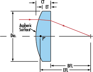
Precision Aspheric Lenses are designed to focus light while eliminating spherical aberration from divergent light sources in applications including focusing the output of a laser diode. Aspheric lenses can increase the numerical aperture of a lens while minimizing system aberrations. Aspheric lenses may also reduce the number of elements needed in a multi-element system. Aspheric lenses can reduce overall system weight while providing advantages such as increasing throughput or simplifying assembly.
Convex Aspheric elements are used to reduce aberrations, apheric lens is ideal for light collection, projection, illumination, detection, and condensing applications.
VIS coating option provides less than 1.5% reflection from 425 – 675nm. NIR coating option provides less than 1.5% reflection from 600 – 1050nm. Contact us for volume pricing of the custom aspheric lenses.

Specification of our Aspheric lenses:
Machining scope
φ5-200mm+0/-0.2
Material
All kinds of optical glass and infrared materials aspheric(silicon,germanium,crystals etc.)
The face accuracy
P-V<0.3 muon m
Surface quality
20/10-40/20
Production capacity
2000 pieces per month
Custom Aspheric Lenses,Specialty Aspheric Lens,Aspheric Cylindrical Lens,Molded Aspheric Lenses
China Star Optics Technology Co.,Ltd. , https://www.csoptlens.com